
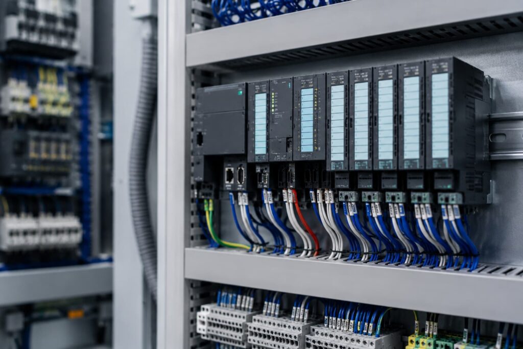

Field signal mapping is where drawings, hardware, PLC logic, and real equipment finally meet. A well-built map tells the control system where each sensor value, switch state, command, and status point belongs. Clear mapping gives integrated control systems a dependable link between plant-floor activity and controller logic.
Signal Lists Create the First Working Picture of the System
Engineers usually begin with an I/O list that records each field device, signal type, tag name, PLC address. Each entry may also note engineering units, alarm limits, terminal numbers, cable references, and whether the point is digital, analog, safety-rated, or networked. Detailed lists help industrial automation system integrators catch missing devices before wiring or programming advances too far. Proper organization also lets designers trace one signal from the process drawing to the controller database without guessing.
How Do Point-to-Point Checks Confirm the Mapping Is Right?
Digital signals are verified by operating switches, pushbuttons, proximity sensors, limit switches, relays, and starters while watching the assigned PLC point. Technicians compare the field action with the HMI indication, controller tag, wiring terminal, and drawing reference to confirm that all four agree. Correct testing can expose swapped conductors, reversed logic, mislabeled terminals, and addresses connected differently from the design.
Unexpected errors often appear because equipment packages arrive with wiring changes, replacement devices, or vendor drawings that differ from the final installation. Skilled control integrators update the map as those differences are found instead of leaving temporary notes that maintenance staff may miss. Documented changes keep PLC logic, electrical drawings, HMI data, and the final I/O list aligned with the installed equipment.
Analog Mapping Connects Raw Signals to Real Process Values
Analog points need more information than a simple address because the controller must know what an electrical value represents. Scaling converts signals such as 4–20 mA or 0–10 V into pressure, temperature, flow, level, speed, or another useful engineering unit. Calibration checks confirm that known inputs produce the correct readings across the operating range. Good mapping also records sensor limits, failure values, precision, and alarm thresholds so bad data is not mistaken for a valid process condition.
Why Networked Devices Need More Than an IP Address
Networked equipment can send many signals through one connection, making logical mapping just as important as physical wiring. Modern drives, remote I/O racks, smart instruments, robots, and packaged machines may exchange commands, status bits, fault codes, speeds, counters, and diagnostics with the PLC. Incorrect byte order, data type, word offset, or bit assignment can leave communication online while the controller reads the information incorrectly.
Managed device profiles and communication tables give an integrator in control system projects a repeatable way to identify where network values enter the program. Consistent tag structures help programmers connect that data to HMI screens, alarms, trends, and sequence logic without confusing one-off references. Accurate mapping also defines what happens after communication loss, including which values freeze, reset, alarm, or force equipment toward a safer state.
Remote I/O Mapping Keeps Distributed Equipment Organized
Remote I/O lets a facility place input and output modules closer to machinery instead of running every field cable to one central panel. Mapping identifies the rack, slot, channel, network node, cabinet location, and related equipment so technicians can locate the physical point quickly. Location-based organization becomes especially useful where identical sensors may sit far apart but appear beside each other in the PLC database. Organized naming shortens service work by linking a software tag directly to the correct enclosure and terminal.
Safety Signal Maps Need Clear Separation From Standard Control I/O
Safety-related points require clear identification because emergency stops, light curtains, guard switches, safety relays, and safety outputs follow different design rules from controls. Dedicated safety I/O may use dual channels, test pulses, discrepancy monitoring, and certified communications that standard modules do not provide. Qualified industrial control systems companies keep these points clearly marked in drawings, software, and I/O records so later changes do not blur the boundary between production control and safety functions.
Redundant channels must be mapped as related signals because the safety controller often compares their timing and state. Testing confirms that each channel reaches the intended safety instruction and that faults such as shorts, open circuits, or mismatched contacts create the expected response. Careful records also show which devices share safety zones, which outputs they remove, and what conditions must be met before equipment can restart.
Commissioning Turns the Signal Map Into a Reliable Plant Record
Commissioning brings the mapping process together by checking field devices against PLC tags, HMI displays, drawings, network data, alarms, and machine behavior. Cross-checking these references removes small mismatches that could remain hidden until a shutdown makes them harder to diagnose. Final documentation gives plant teams a dependable record for troubleshooting, expansions, replacements, and programming changes across integrated control systems. RL Consulting offers field signal mapping services that can help facilities accurately connect sensors, actuators, remote I/O, PLC tags, networked devices, and HMI data across integrated control systems, providing a clearer foundation for commissioning, troubleshooting, and future system changes.